Closed Circuit Television/Camera System manufactured by EMI Electronics in the 1970s.
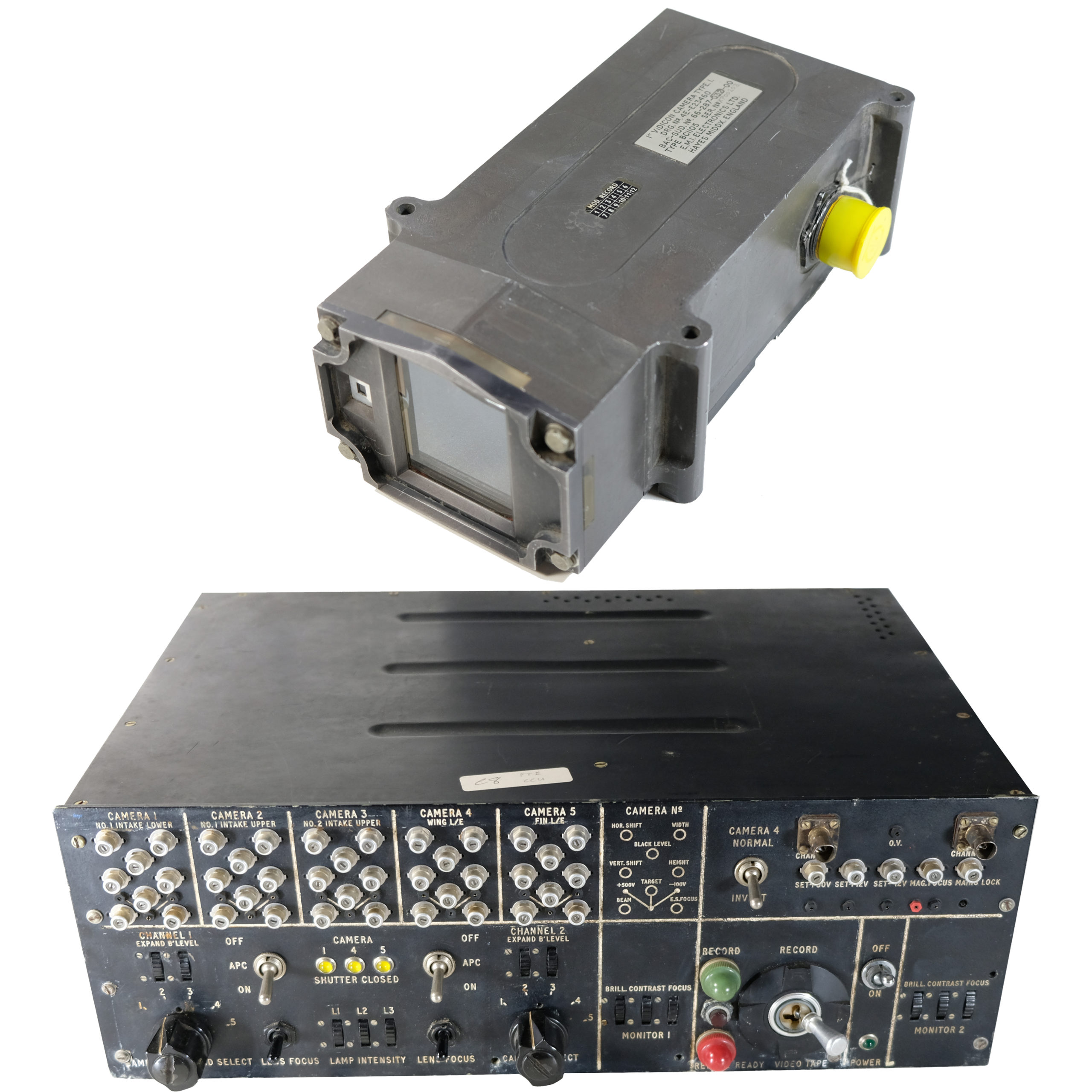
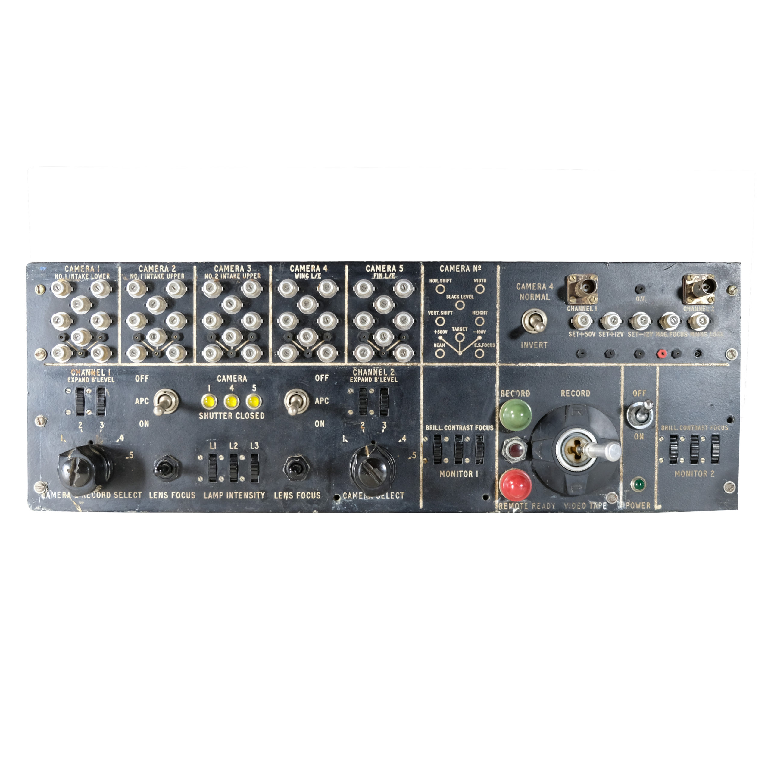
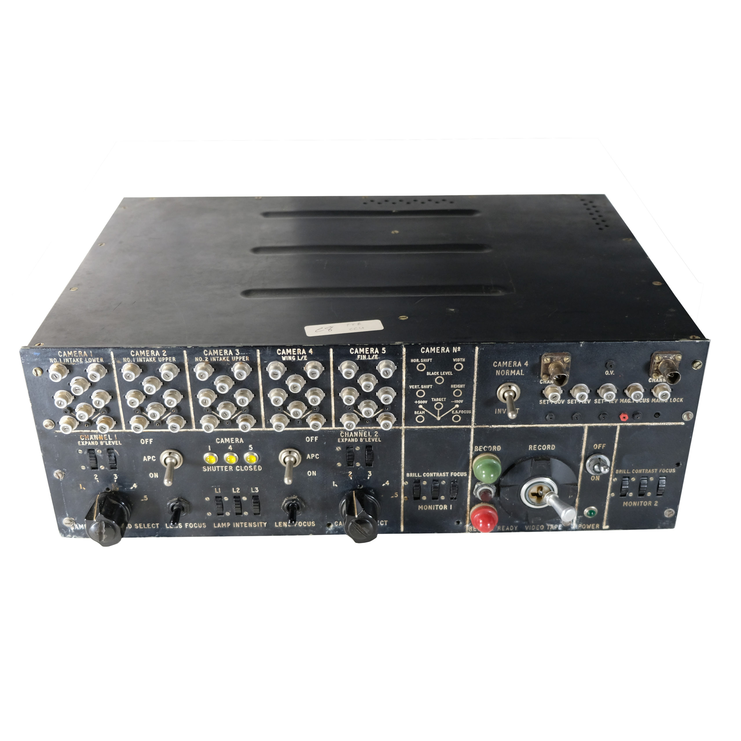
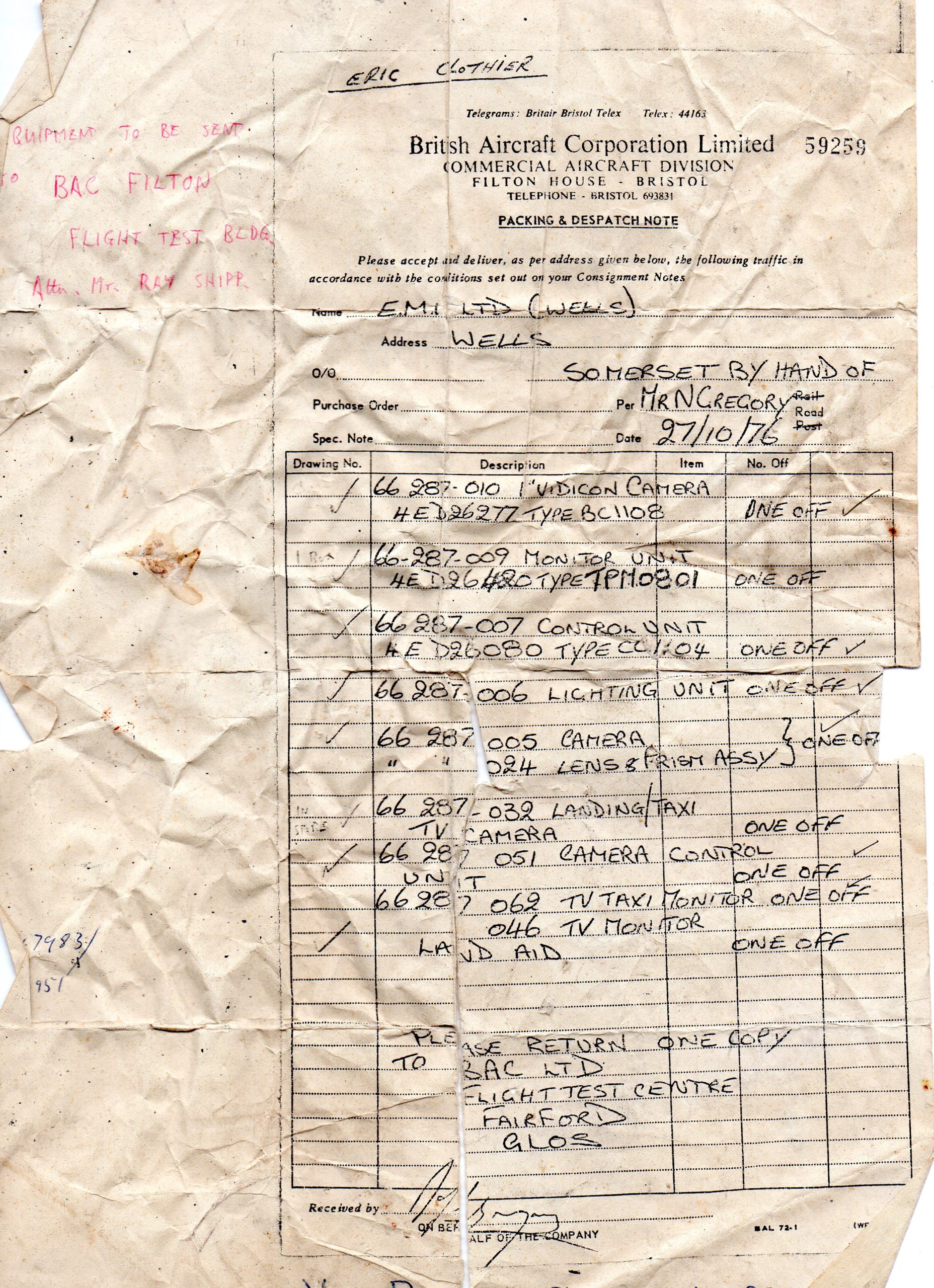
This is a bundle of items that together make up the main parts of the external camera system used on the test flights of Concorde in the late 1960s and 1970s. The system of external cameras allowed the flight test engineers onboard to observe key external surfaces and features with cameras positioned on the air intakes, wings, and fin. To quote the first paragraph of the operating manual for the system:
“The CCTV system described in this manual was designed for flight test purposes in the Concorde prototype aircraft. It enables the flight test personnel to observe during flight, by means of TV monitors, certain vital parts of the aircraft exterior to watch the build-up and recession of ice. The system also provides outputs suitable for an Ampex Video Tape Recorder (VTR) so that, if required, a video recording of the conditions at any of these vital points (selected one at a time) can be made.”
Part of the documentation that we have dated 1st July 1968 also describes it as ‘Concorde Taxying – Landing Aid’. In practice we understand that it was used for both purposes.
A full review of the system was published in in 1970 Aircraft Engineering and Aerospace Technology in 1970
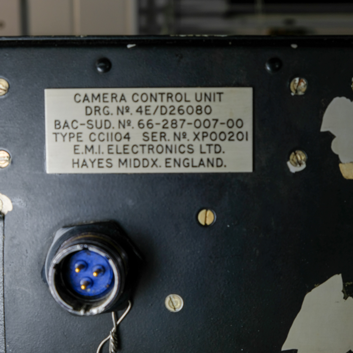
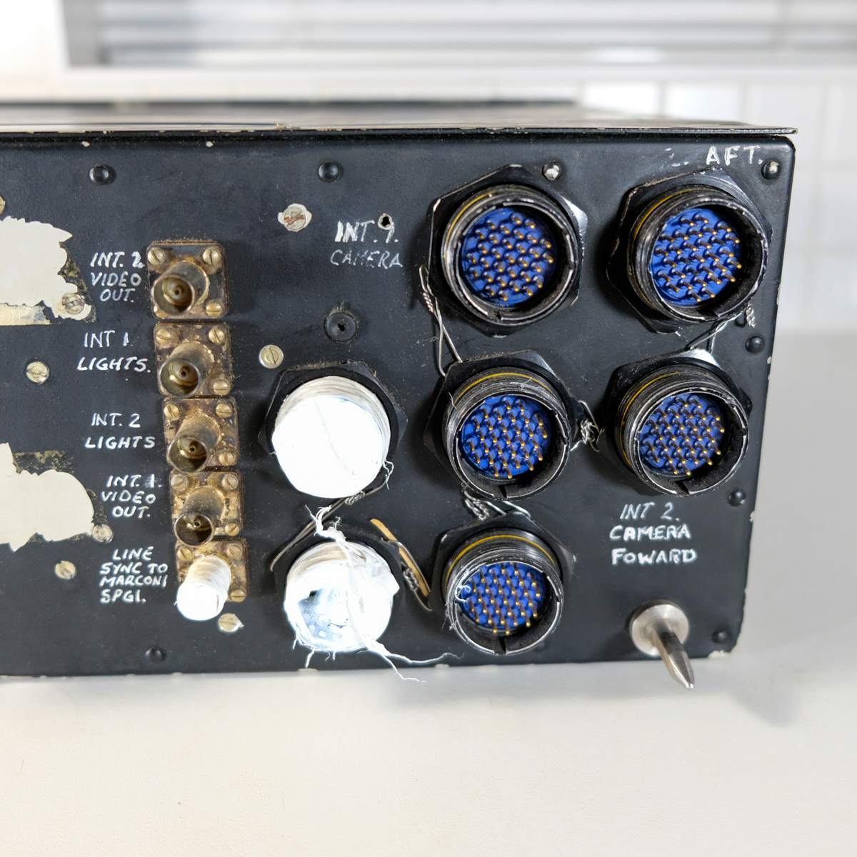
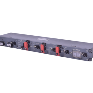
Camera Control Unit. This is a heavy black painted metal unit with numerous switches to the front and connectors on the front and rear. It measures 43cm wide x 15cm high x 31cm deep and weighs around 10kg. It was powered by the Concorde 115V system Now around 55 years old it would be a brave move to try and turn it on (at absolute minimum we would expect all capacitors would need replacing), but the fascia contains many lights and re-activating some of the switches and lights to light up again via a suitable low-voltage feed should be possible. Concorde Equipment Code: 66-287-007-00
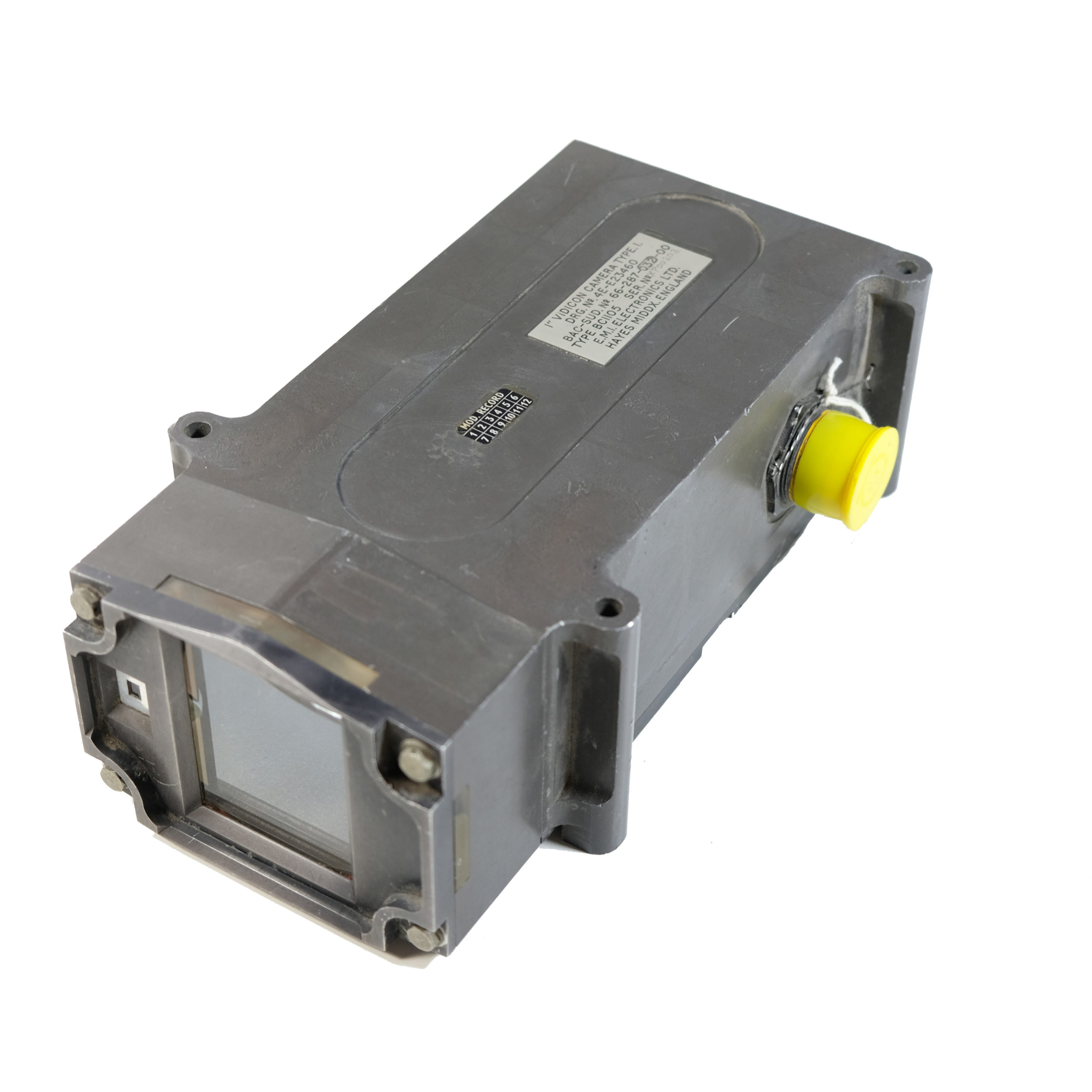
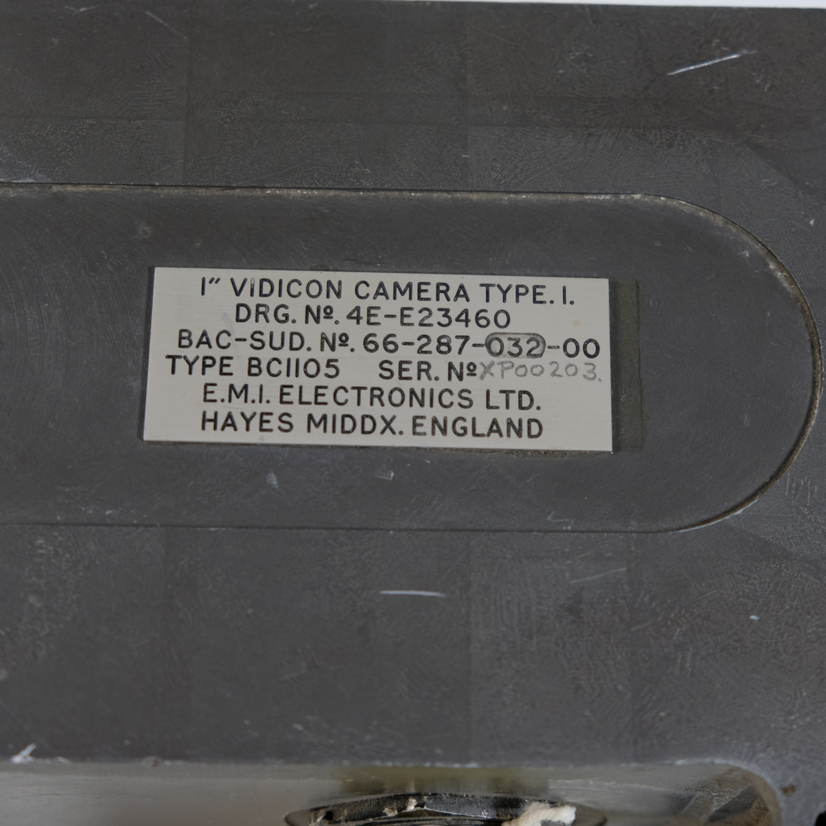
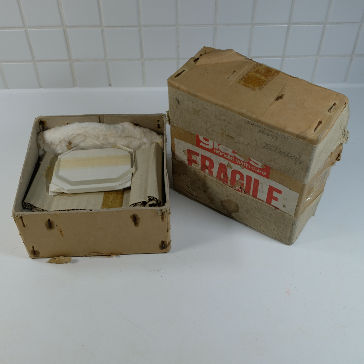
Vidicon Camera Type 1. Essentially a stripped down and strengthened TV camera of it’s day in an very strong milled metal casing with extra protective glass on the front designed to withstand the extreme temperatures and pressures it would encounter. The front glass has a crack in it but this bundle includes a box containing 3 spare glass fronts which look to be simple to fit! This camera was fitted to either the leading edge of the port wing or the leading edge of the tail fin. Concorde Equipment Code: 66-287-032-00
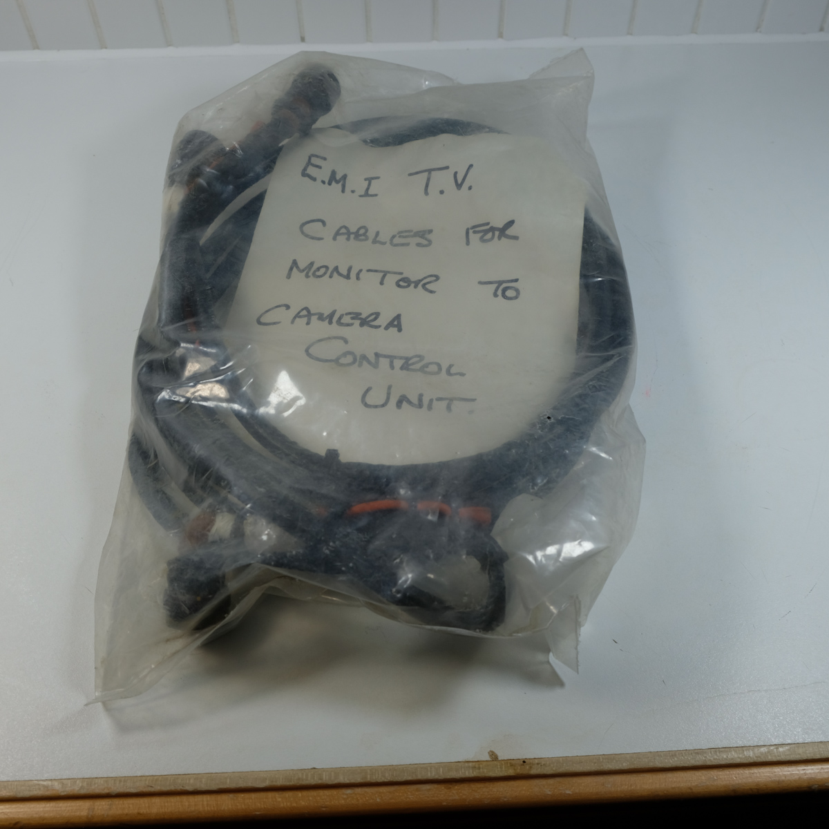
Cable: EMI TV Cable for connecting the CCU to a monitor.
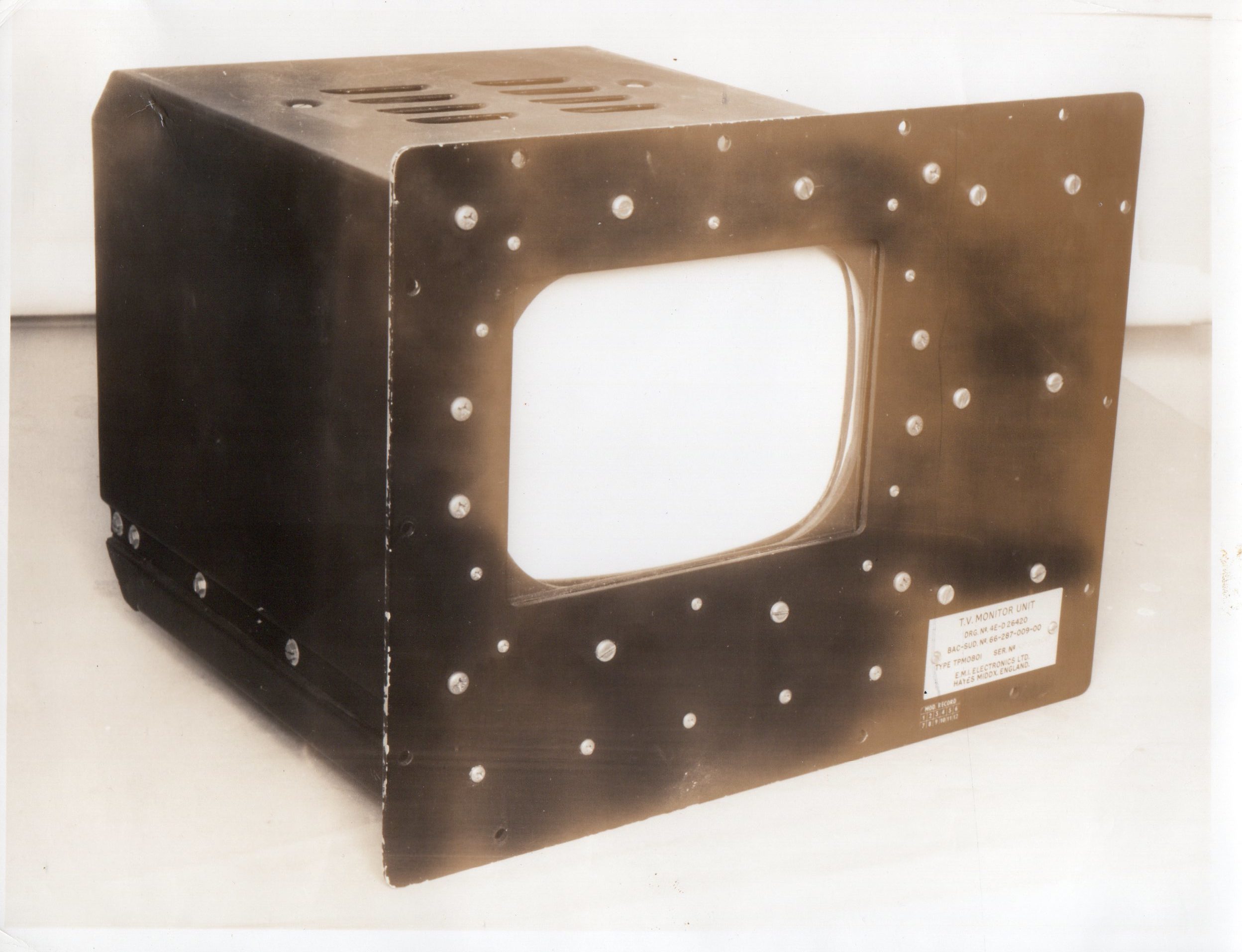
TV Monitor: We do not currently have this item. We have an original photo of it (please see the image gallery). We also have the full technical description and engineering drawings for it. It is essentially a standard EMI TPM0801 8 1/2″ CRT screen fixed into a metal chasis. (See photo). If the original cannot be located or acquired then a replica could be created using the engineering drawings and photo – possibly using period components where available.
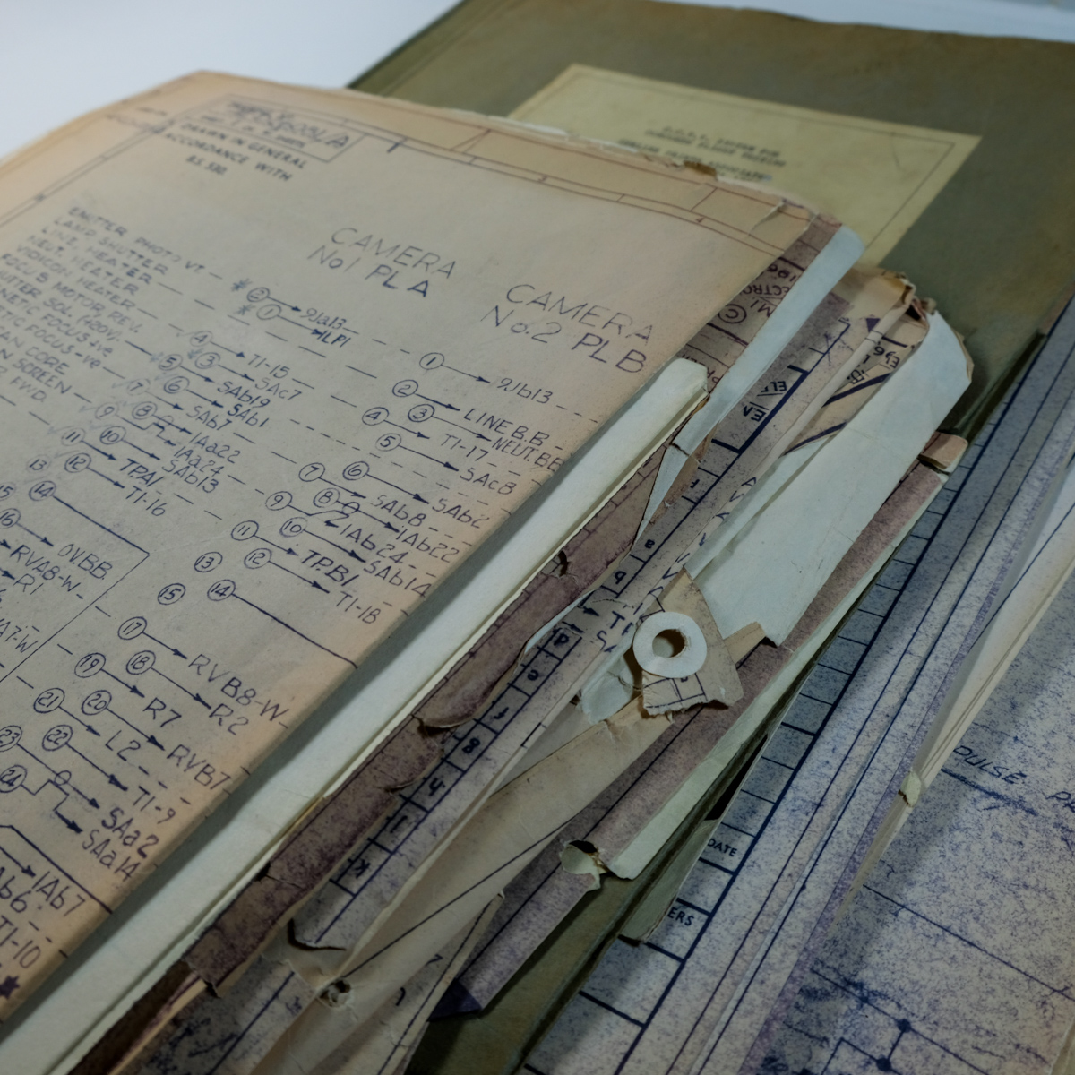
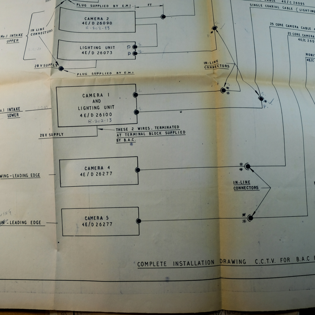
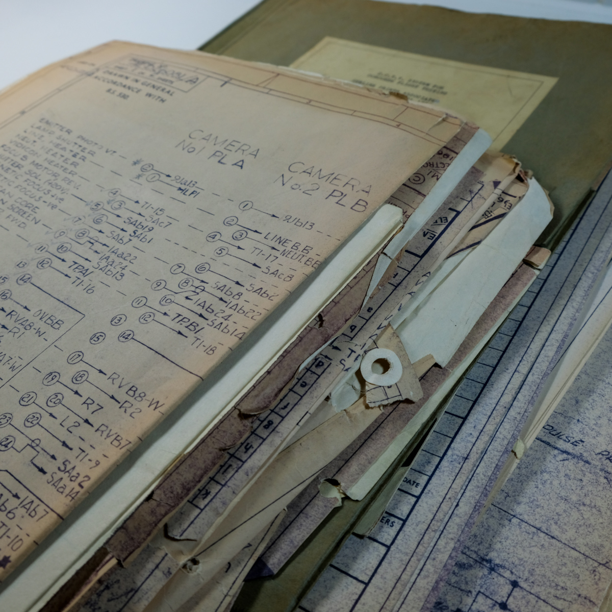
Engineering Drawings. This large collection of around 25 original blueprints (a mix of ‘D Size’ and27 1/2 ” folded) in a folder titled ‘C.C.T.V. SYSTEM FOR CONCORDE FLIGHT TESTING’.
System Manual: An approx 100 page manual detailing the entire system and it’s operation.
Bill Of Materials: Around 25 sheets detailing every component with both the Concorde and manufacturer’s reference numbers.
Status: SOLD – Currently on display on G-AXDN at Imperial War Museum Duxford. As an important legacy collection from the test flights we were keen that the items stay together and it either ends up in a museum, heritage organisation or with a collector that can make it available on loan to such an organisation. The final photos show the team at Heritage Concorde installing these pieces on G-AXDN. Find out more about their work here: https://www.heritageconcorde.com